Introduction to Profile Projectors or Optical Comparators
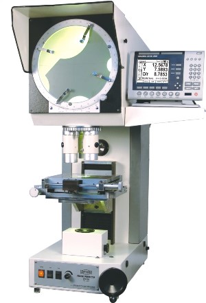
A Profile Projector also called as Optical Comparator or a Shadowgraph Projector is a specialized measuring system which is broadly classified under the category Industrial Metrology Systems. It is a versatile and indispensable measuring system in the manufacturing sector where small parts two dimensional measurements are required in the R&D, Production or Quality control departments. Automotive parts, plastic and rubber parts, wire and cable, biomedical equipment are some of the manufacturing industries which extensively use profile projectors for day to day measurements.
Principle & Construction
An Optical Profile Projector beautifully combines optics, mechanics, electronics and software to provide small parts two dimensional measurements.
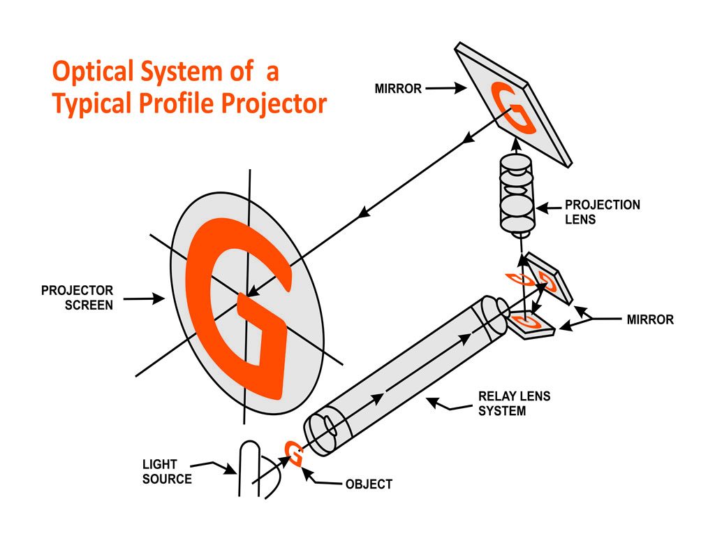
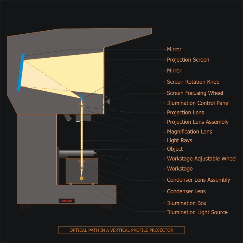
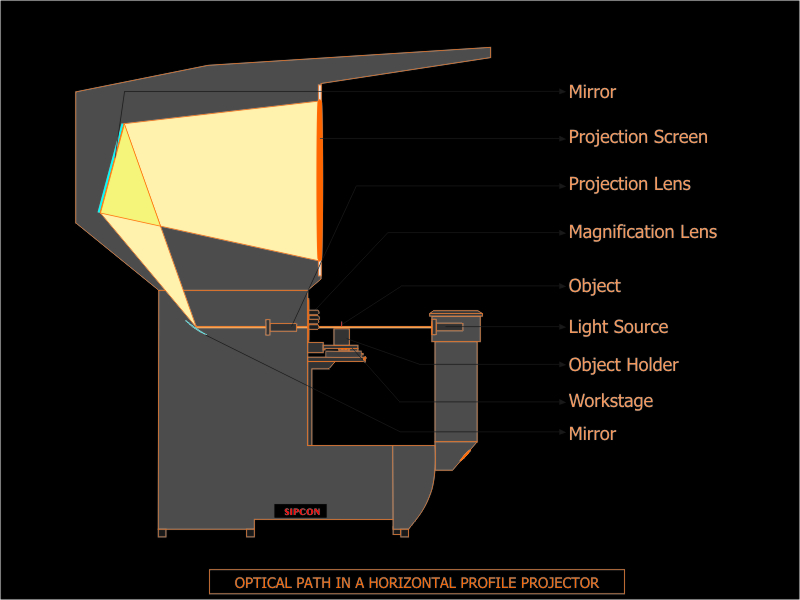
A beam of parallel light, produced by a tungsten or filament lamp (and with a large enough diameter to provide coverage of the test piece) along with a system of condensers, lenses and mirrors is used to create and project a shadow of the test piece onto a built in projection screen. The optical system magnifies the profile of the small part, making it easy to do measurements. Depending upon the light path Profile Projectors are further classified as Vertical Profile Projectors or Horizontal Profile Projectors.
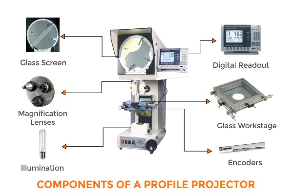
The built-in table on which the test piece is kept is called a work stage that can be moved in x-y directions and have integrated linear encoders to precisely measure the x-y movements which are then displayed on a digital read out or a computer screen using metrology software.
The operators using their visual acuity and perceptiveness identify and mark a reference point on the shadow (screen has cross hair reference). They then move the work stage along the length of the shadow, the dimension of which is to be measured. Alternatively they can identify and mark points, and the system automatically calculates the distance, angle, arc length, etc. of the shadow and consequently calculates the same for the part.
Evolution of Profile Projectors led to the invention of Vision Measuring Systems or a video Measuring Machine which use a digital image of the part (instead of a shadow as in Profile Projectors) and automatic edge detection to do more precise and accurate measurements.
History of Profile Projectors
1922 – 1930 –The first Profile Projector used as optical Shadowgraph Projector: Invented by James Hartness President of J & L Machine Company in 1922 to standardized the screw thread sizes by measuring the complex curves of screws. The first Profile Projector projected the shadow of the object on a screen which was few meters away and then the measurement of the shadow image of the screw was done against the drawings that is why the term was coined Shadowgraph Projector. By the end of 30’s it was integrated into a single machine and was used for setup inspection during manufacturing.
1930 – 1940- Industrialization of Optical Profile Projectors : J & L Machine Company started exporting the Profile Projectors to Soviet Union where there was very fast industrialization under the leadership of Josef Stalin. Application areas now included bottle moulds, razor parts, small parts etc. The sales were around 300 units per year.
1940 – 1960 – Profile Projector application in automobile industry : A very strong boost to the sales of optical comparators was provided world war II as Profile Projectors were used for manufacturing of every part used in World War II as a standard for US Artillery. Also the Profile Projector become a common name in Automobile and Aircraft Industry. Accuracy improved because of better lenses and reflectors.
1960 – 1970- Profile Projectors with optical edge sensor and linear encoders: Automatic edge detection was added which removed the operator errors in detecting the edge. The subjectivity elimination in finding the edge resulted in improved accuracy. Rotary encoders gave their place to linear encoders and the big issue of back lash was resolved. The problem with the Rotary encoders was that the measuring accuracy was dependent on was the thread of rotary encoders, even a slide mismatch or wear and tear in between the gears can cause measuring errors.
1970 – 1980 – Digital Profile Projectors: Digital Readouts (DRO’S) were introduced and this made the reporting much more easier as apart from the linear and angular features it was now easy to measure the radius and diameters also.
1980 – 1990- Fully programmable automatic Profile Projector: Programmable motion control system resulted in motorized stage control thereby increasing the speed for the measurement. The Profile Projectors were now being used as fully automatic machine which could incorporate the programmable functions.
1990 – 2000 – Profile Projectors for reverse Engineering: Software’s were introduced to the optical comparators and the computer base systems helped in comparing the data with the CAD file. Reverse engineering was much easier now as the Profile Projector software’s were able to export the drawings into the popular CAD software’s. Not only the software increases the capability of the optical comparator but also made it easier for operators to use the special features of software like reporting and programming.
2000 – 2010 – Introduction to Camera Based Profile Projectors: Reflective scale technology was introduced which eliminated the backlash (if any) from the linear scale technology. Also camera based Profile Projector systems were added to the Profile Projectors to improve the edge detection and image quality when surface elimination is used.
2010 – Till now- 3D Profile Projectors : Traditionally the Profile Projector was used only for 2D measurement, 3 D measuring capabilities like touch probe was added to make it capable doing Z axis measurement.
ABOUT SIPCON INSTRUMENT INDUSTRIES
Benefits of Optical Profile Projectors
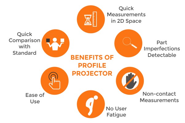
- The ability to measure in 2D space in which both length and width of the part can be measured simultaneously results in quick measurements.
- Imperfections on parts such as burrs, scratches, indentations can be detected on profile projector.
- Delicate parts that might deform on touching can be easily measured on a profile projector as no-contact is required for measurements.
- Ease of use, requires minimum amount of training.
- No user fatigue as unlike measuring through a microscope, the user does not have to look through an eye-piece for long hours. Moreover, the profile is visible on a big screen so that the team members can look at the image and can discuss about different part dimensions.
- It requires minimum maintenance for functioning; however calibration needs to be done every year.
Types of Optical Profile Projectors
- Classification based on Light Path: Depending upon the light path the Profile Projector can be classified as a Vertical Profile Projector or Horizontal Profile Projector. The former is used for light weight part inspection and the latter is used when the part to be inspected is heavy like shafts etc.
- Classification based on type of optics: Normally in the profile projector the surface illumination is from sides which sometimes may affect the image clarity in case of deep cavity components. Coaxial Profile Projector as the name suggests has special optics with built in half reflecting mirror in the lenses so the light actually is coaxial with the path of the lenses i.e it comes through the lens thereby making the deep cavity inspection easier.
- Classification based on Application: If the profile projector is used for comparing the shadow of the work piece with the Mylar or charts then it is generally referred as optical Shadowgraph projector and when it is used with DRO or Software for measurement then it is referred as an Optical Profile Projector.
Types of Profile Projector Optics
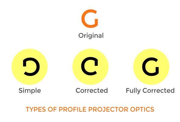
Simple Optics vs Corrected Optics vs Fully Corrected System
In simple optical systems the image on the profile projector screen is both up-side down and reversed. For symmetrical parts this system is best suited as there is no difference in the both the horizontal and the vertical mirror images.
In corrected optics systems the images produced are unreversed , however they are still upside down. This system is best suited for asymmetrical parts, if it is important to know which side is being measured so that there is no confusion in operator’s understanding of the measurements.
In Fully Corrected Systems the images displayed on the screen are both erect and unreversed, this make measuring very convenient for even the inexperienced operators.
Profile Projector/ Optical Comparator Comparison
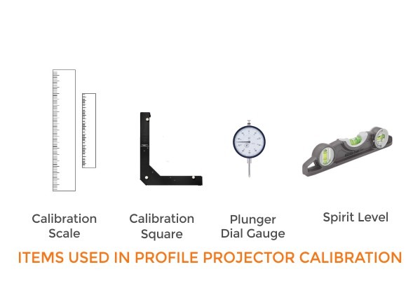
Profile Projector / Optical comparator Calibration
Repeated use of Profile projectors over time can make the system go out of calibration. Therefore it is required to re-calibrate them every year. A typical calibration routine involves the following:
- Focus squareness parallel to optical axis.
- Table squareness perpendicular to optical axis
- Perpendicularity of X to Y axis.
- Magnification and distortion accuracy for all lenses
- X-Y axis lead accuracy for the complete length.
- Edge detection accuracy
Measurement Options : DRO vs Metrology Software
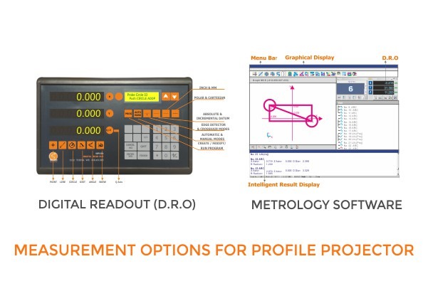
The two most popular measurement options are Digital Read Out and Metrology Software. Below is a comparison of the two options.
[table “29” not found /]